Blue Lantern Advanced Yarns. Sounds pretty neat right? BUT FIRST.
No more long winded posts! Just some spicy PCB shots and things that might be helpful to others… for the most part.
Because I recently grabbed a Digitakt, I now need something to take advantage of these sweet sweet MIDI tracks in the Eurorack world. Enter Yarns.
I tried to get mBrane.. the tiny little Yarns, but Pusherman only had a single PCB left. I decided to go with Advanced Yarns instead. BUT GET THIS. In my package from Pusherman they included the single mBrane PCB for free. What a sweet pea that Pusherman/Phil is. Thanks a bunch, if you ever read this.
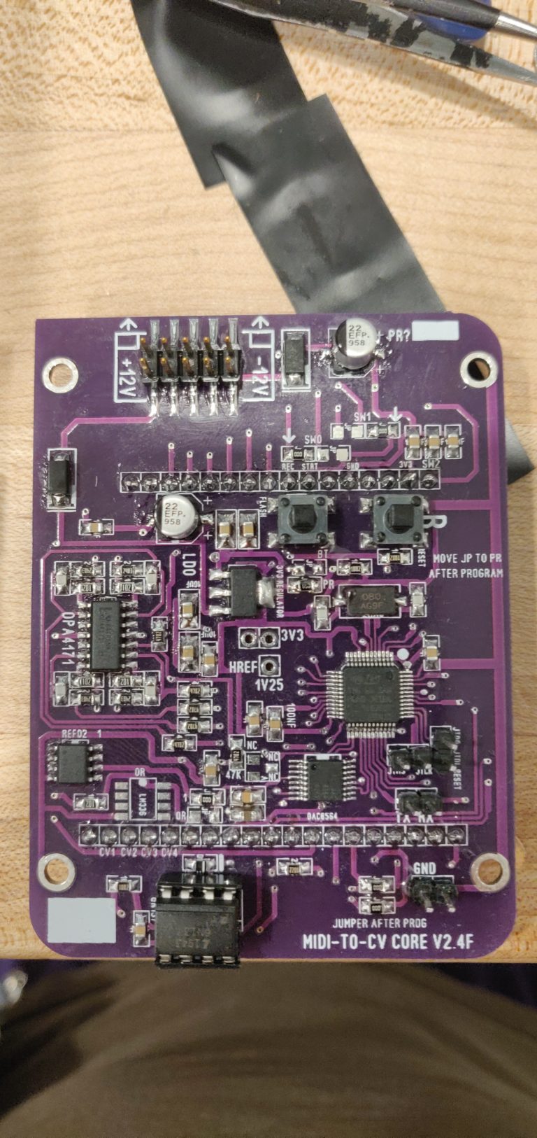
First, I’ll start with the Core PCB. It seems like the four 10u caps used here are 1206 footprint, although the BOM reads 0805. Because 0805 fit just fine it doesn’t bother me, but if you’ve got PCB OCD, don’t make that mistake.
Second, let’s talk software. Flashing this guy was a journey. Mostly because I had to try a few different computers before I got it going . This was the process I ended up using.
- Get the core PCB built (or at least the MCU, power sections, as well as the two push buttons).
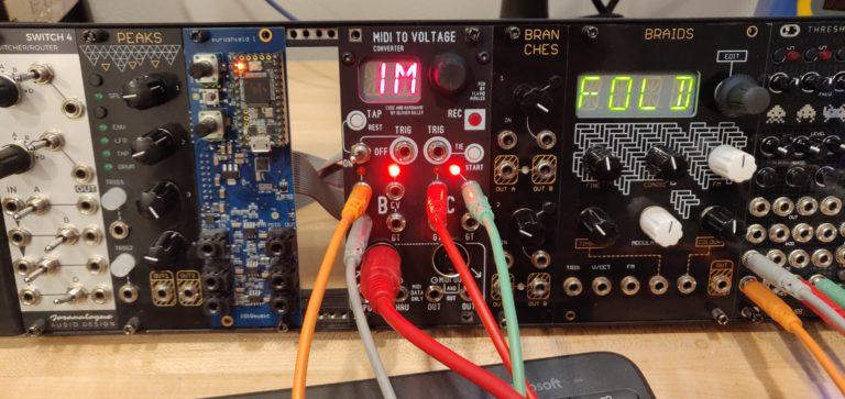
- Check jumper placement, set to flash by having the single jumper on “BT”. In the above shot the board has been flashed and the jumpers have been moved from the flashing position.
- Grab an FTDI dongle, most places recommend FTDI Friend, I grabbed this FTDI Dongle
- Connect Euro power, connect TX, RX and Ground pins with FTDI dongle. (RX and TX need to speak to each other, so remember to connect: TX on FTDI dongle to RX on PCB, and RX on FTDI dongle to TX on PCB)
- Start mutable dev environment
- Navigate to “eurorack-modules”, then “stmlib”, and change the PGM_SERIAL_PORT ?= variable to PGM_SERIAL_PORT ?= /dev/ttyUSB0
- Compile the bootloader and firmware:
make -f yarns/bootloader/makefile hex
make -f yarns/makefile - On the PCB, prepare the chip for flashing. Press the “R” button for 1 second. Let go, press and hold the “R” and “F” buttons for 3 seconds. Let go of the “R” button and hold the “F” button for 5 seconds.
- Flash using the following command:
make -f yarns/makefile upload_combo_serial
- If you receive any “can’t INIT” messages, try from step 8 over again. The chip may not have received the “time to flash” message from the button presses.
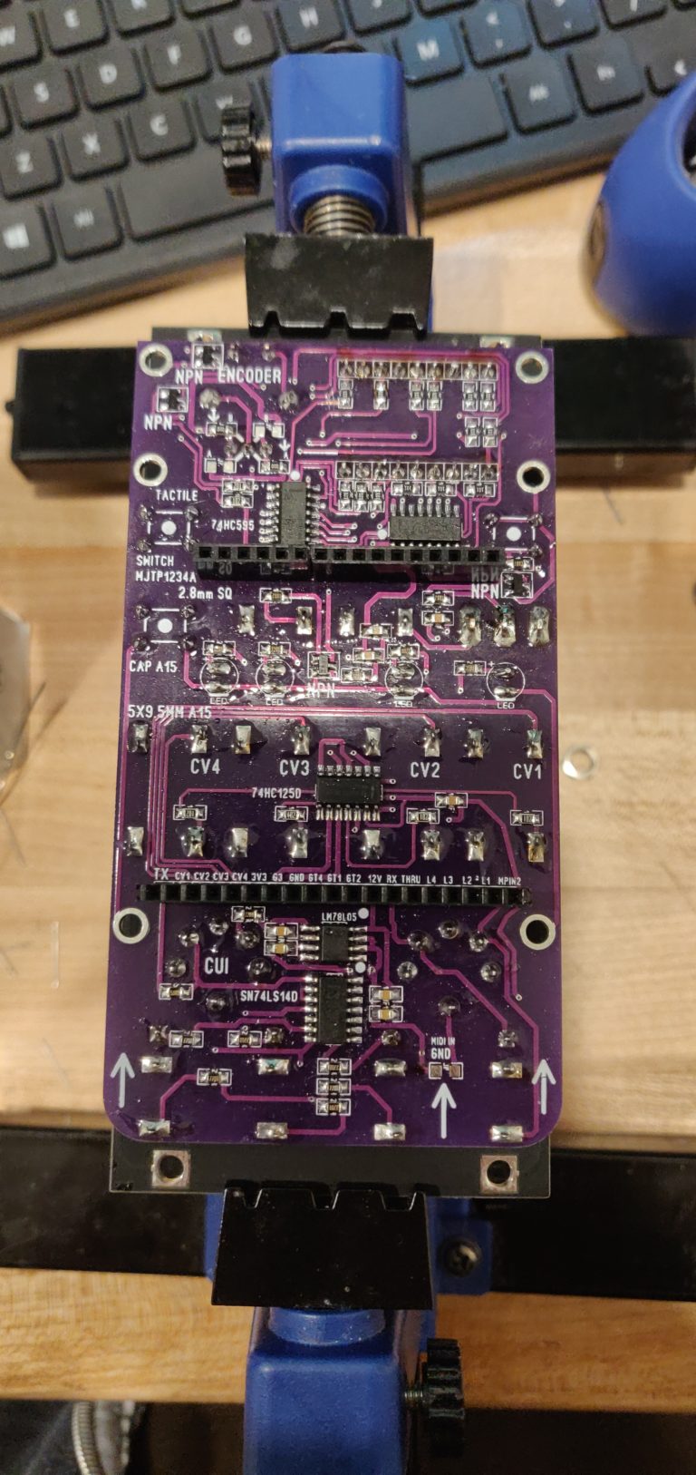
And third, as far as the controller PCB goes, what a little trip this was. I’m starting to understand why this thing is an “Advanced” Yarns. I was looking for the ground on the CV/Gate jacks, as well as the 2 trigger jacks… and I could not find them. Turns out, the panel grounds these jacks through the sleeve. I am not sure if it is visible in the picture, but the panel has a route to ground from these jacks. I snipped the ground legs then soldered like normal.
The above picture shows the jacks all in, but all in… backwards. Because I misread the PCB , I ended up having to pull out all 10 top jacks… that was NOT the best time. But boy was I happy when the CV jacks started CV’ing!
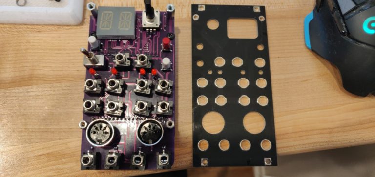
And finally, that’s it! Advanced Yarns! It is hooked into the Digitakt and I can’t wait to spend the next couple days learning how it works. Very gnarly module.
Maybe I’ll start doing something with a slightly larger demographic…Audio plugin reviews? I just want internet attention is all. Also, I am shocked I’m not winning Pulitzer’s over these Advanced Yarns’.
Quick Links
Mouser BOM – No jacks, no LEDs, no hardware (standoffs, screws)
One small addition months later. A reader named Tom Marshall made this comment and I think it would be helpful for anyone else trying to build one of these:
For standoffs between the controller PCB and front panel, 13mm would seem about right to get the MIDI Din sockets flush, (although 12mm would make the 3,5mm jacks easier to install) Then it looks like 2x 9pin SIL headers bring the LED display up to the same level as the Din sockets otherwise there’s quite a gap.
I personally used 10mm standoffs, but my PCB is a little squished and the MIDI jacks are not flush. I’d recommend following Tom’s advice and getting 13mm standoffs between the controller PCB and front panel.
Great to find this, I’m about to start building one myself. PCBs arrive from Pusherman next week.
I’m presuming that you can program using the HEX files here https://www.bluelanternstore.com/uploads/6/2/8/9/62894835/public-mtcv-v5-10hp_confirmed.zip ?
What size hex standoffs did you use, M3 10mm ?
Hey Tom, thanks for reading. I didn’t personally give them a try, but those HEX files look good to me!
And yes! M3 10mm standoffs will get this thing stuck together nice’n’good. Best of luck on the build, send me a message if you run into any issues, and be sure to post some pictures when it’s complete!
Hi Steve, All good so far ! Everything done, doing the through hole stuff as the assembly goes together to get everything flush on the front panel. Programming firmware in the next few days when the 8MHz crystal turns up, think I’ll try doing it via JTAG first with an ST-LINK V/2 as there are JTAG jumpers on the PCB.
For standoffs between the controller PCB and front panel, 13mm would seem about right to get the MIDI Din sockets flush, (although 12mm would make the 3,5mm jacks easier to install) Then it looks like 2x 9pin SIL headers bring the LED display up to the same level as the Din sockets otherwise there’s quite a gap.
Then there is the 12 week lead time on the A15 tactile switch caps, couldn’t find any on short lead time.
Happy to post some pics, html links in this text ?
That is great to hear! Lead times are killer lately… but you will have some of that MIDI magic happening real soon.
Thanks for the tips on the standoffs, is it OK if I mention this in the blog post?
And HTML links sound great, looking forward to it. Hope your parts show up soon, until then, take care!
Hi Tom. I’m just about to hook up my Yarns build to my ST Link. What software did you use to upload the hex files ? Just GND, JTMS and JTCK connections ? Is there a sequence for the bootloader and the firmware ? Thanks !
Yep, when I get the standoffs, jack sockets and switch I’ll assemble it all up to try and get the best arrangement I can. I think that fitting 6 standoffs between the controller PCB and front panel ( even though you can only fasten 2 at the top of the front panel ) is a good way to get those boards parallel. Then with the LEDs, sockets and switch fitted to the front panel you can solder everything in. That’s the plan anyway.
Will take some photos of that so you can share the info. Used a USB microscope to check the STM32 and ADC too, very inexpensive way of checking for dry joints/solder bridges etc
Hi Steve,
Meant to post this some time ago. Photos of build are here: https://www.dropbox.com/sh/927r6pwsii2ntnn/AABrSPIejZrpjmpI-fR-P9KTa?dl=0
13mm standoffs between front panel and control PCB work. SIL headers to mount the LED display reduce the gap and the 3.5mn jack sockets *just* reach but this is very fiddly. You can’t mount these in the PCB so it takes a while to line them all up. The slots in the PCB help a lot !
Also I needed to design my own tactile switch cap and 3D print it, you can’t get a standard one that’s long enough ! STL file included in the link for a row of 10 caps. Either SLA or SLS printing will work for this part but don’t try FDM.
All been running fine, but today I tried to calibrate and the software seems to hang up. Have you tried this ? After I set the first -3.0V adjustment, turn the knob to select the next voltage and it freezes.
Cheers,
Tom
Thank you for all your pointers! Really appreciate you coming back and updating us.
I calibrated both my M-Brane and Advanced Yarns without issue. Could be a firmware issue? Maybe try flashing a different version. Or check the soldering on some of the ICs?
Best of luck! Thanks again.
Hi Steve,
” On the PCB, prepare the chip for flashing. Press the “R” button for 1 second. Let go, press and hold the “R” and “F” buttons for 3 seconds. Let go of the “R” button and hold the “F” button for 5 seconds.”
Can I ask where you got this information ? I have an ST Link v2 and am about to try flashing the firmware binaries using STM32Cube.
Hi Mark! Thanks for reading :). I am sorry, I do not recall where I found this information, but this is the procedure for putting the device into a state where it can be flashed regardless of the software you use. I can’t speak to STM32Cube; but I do highly recommend using the mutable-dev virtual machine to flash the device. It makes the process much easier!
Hi Steve. Thought I’d check in with an update.
I used an FTDI friend and switched to the Mutable dev environment as you suggested.
After 30-40 attempts, I finally got the STM to flash. Sadly, I have no idea why it worked that time, because I wasn’t doing anything different, so my only advice to anyone reading is “persevere” !
After getting the STM flashed I had a couple of more problems – here they are with solutions for any future readers.
(1) My encoder was registering clicks but not rotations, no matter how I set the jumpers. This turned out to be a “grounding” problem. The two big lugs on the back of the encoder need to be soldered into their holes in order to complete the ground circuit for the encoder pulses. I don’t normally solder these so it took me ages to find. Absolutely infuriating.
(2) Intermittent failure of outputs. After checking continuity from the DAC outputs all the way through the op amp to the CV outputs multiple times, this also turned out to be a grounding problem. As you mention above, the sleeves on these jacks are grounded through the panel. My problem was that 6 of them were grounded solidly through the panel and two were 50/50. I ended up just wiring all the grounds up behind the panel just to be sure.
Thanks again for this page. I am 100% certain that I would not have a working Yarns if it wasn’t for your information.
Good luck on your next build !
Just saw this now, thank you for sharing your experience! That is fantastic to hear that you got your module up and running. Perseverance is truly a virtue, and you clearly have it in spades (30-40 attempts :O ). Happy that this website can be a resource to people. Even if it just helped you, Mark, definitely worth the hosting fees. Best of luck in all your next projects!!