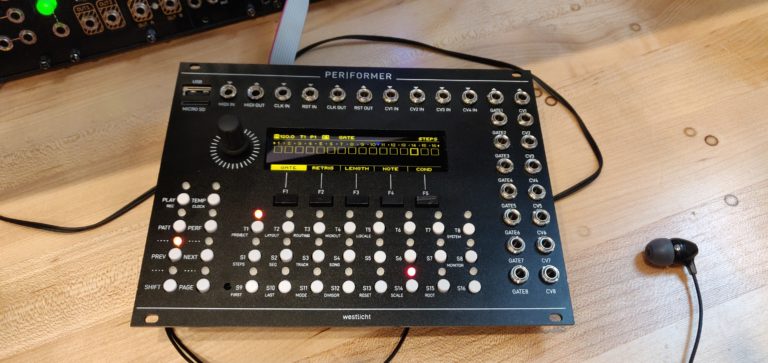
OHHHH man was I excited about this one, and, SPOILERS, it did not disappoint. Look at it, in all of its glory.
It took a fair bit to get here. It wasn’t the most difficult build (thanks to the amazing build guide), but I made a couple of sleepy errors, and had some broken components that gave me a some trouble. Either way, lets get into a not very detailed, semi-helpful, terribly documented walk-through of my build!
The build guide that Simon (the creator of the PER|FORMER, yes we’re on a first name basis now that I’ve built his module and have had no contact with him otherwise) is really great. I really can’t understate this. The interactive BOM, the suggestions as far as building the power sections, then the MCU sections and getting your test on. It’s fantastic. It would be great for people who are into DIY, but aren’t sure what melting these tiny pieces together actually does. But don’t get me wrong, it’s not for first timers. If you’ve made a couple through-hole kits maybe look elsewhere before attempting a build like this.
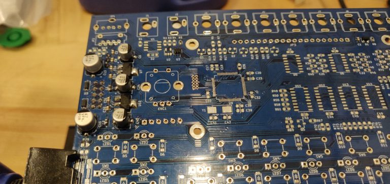
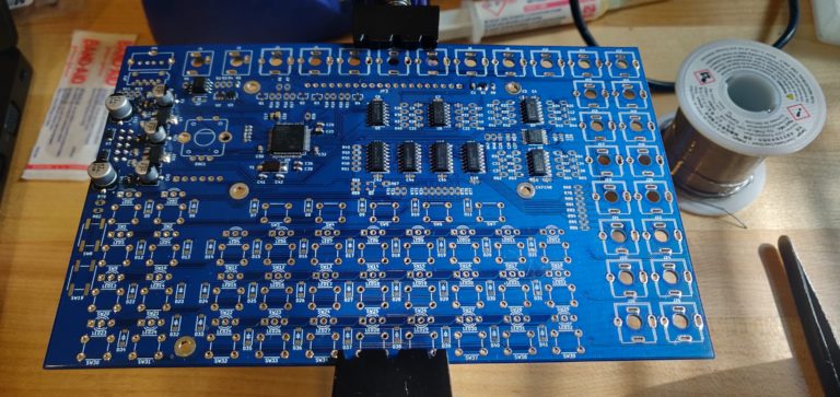
Enough gushing. Let’s get that power section in there.
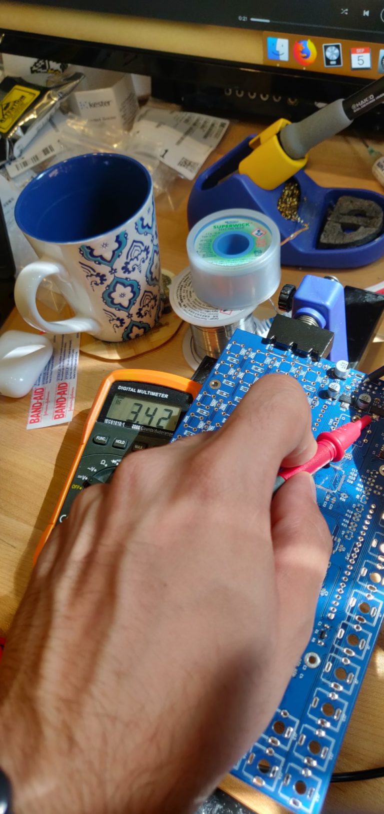
Now that we have all the necessary components to provide power, I took out my trusty multi-meter and started testing all of the power rails. I made sure I was seeing the proper voltages in the proper places.
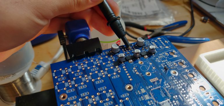
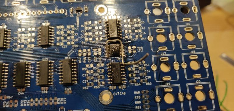
Then I took the single most difficult picture I have ever attempted, all just to get a little visual on this action…
This picture was actually easy... Get that ground pin with your multimeter...
I had to balance the camera on a scarf... this is this best you'll get outta me. Maybe I'll invest in a tripod...
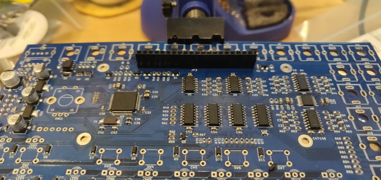
Now that the nightmare of a photo shoot is over, we can move onto the MCU section, because all of the power rail readings came back A-OK.
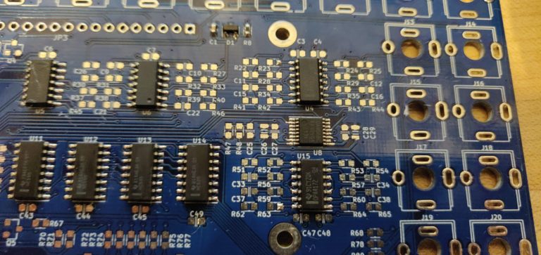
I also did the rest of the chips while I was at it, because it was late and I wanted to make a little more headway on the PCB. I woke up the next morning and snapped a shot…
Great, looks like some clean work. Let me double check these guys before I move onto flashing, or put any juice through the circuit…
Oh nice, the $25 DAC is soldered in backwards…
I have no rework station, so I resorted to some methods I am not proud of. After wicking up as much solder as humanly possible, I bent the pin of a diode I had laying around to fit the chip. I held it down with pliers and my soldering iron… slowly but surely it started to move….
Then it’s stuck a little further from where I started… After almost 30 minutes at this and way too much flux later, I gave up and ordered a new DAC.
Something funny happens when you give up/buy a replacement part. Something magic maybe. I wicked up what little solder was left, and went to try to pry the chip a little before resorting to snipping the legs.
And it popped clean off. Excitedly, I flipped it back around and soldered it in.
Let’s hope it works. (YOU KNOW IT WORKS YOU SAW THE PICTURE AT THE TOP).
On to flashing the MCU.
Keeping up with the unreal pedigree of this build and documentation, Simon created a vagrant environment much like the mutable-dev-environment. A beautiful walled virtual machine garden that flashed my MCU without issue. Well done Simon, well done.
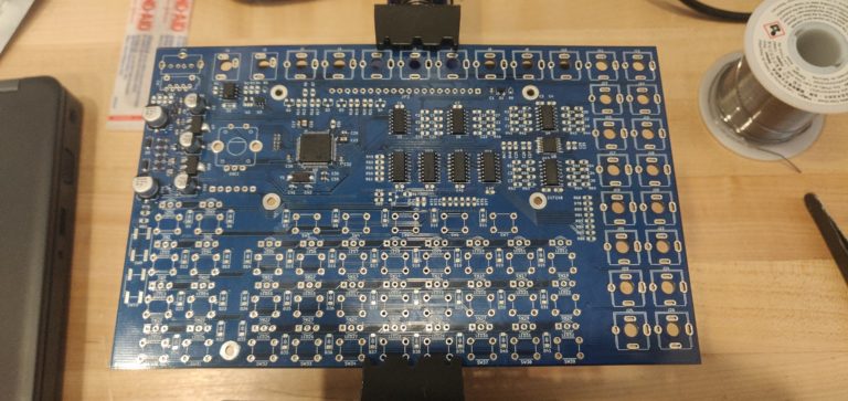
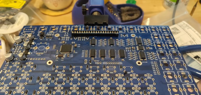
Looking like a brand new PCB with a flashed MCU. Look how the processor sparkles...I really should have moved that band-aid...
From here on out it gets a little less exciting. As always, I went for the smallest components, 0603 caps and resistors.Then I placed the rest of the smaller ICs, then the WHACKLOAD of diodes.
Now were almost at the end of the rainbow, time to get the hardware components on there.
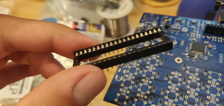
First thing I wanted to check was the socket for the LCD. I grabbed a DIP socket and cut it in half, as regular headers had the LCD sitting far too high, even after trimming the pins.
Looking beautiful. At this point my need to sequence gate and CV over 8 separate tracks is palatable. People next door can feel the soft hum of my voltage induced desires.
If you got this far in you deserved to read something weird. Congratulations.
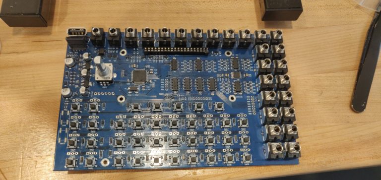
Let’s get the rest of the hardware on this puppy.
Not that you would read this before the build guide, but it’s a must to make sure you plug a USB cable in through the panel when you solder the jack to the PCB. Don’t want any misalignment once everything is stuck in there. Use a spare/garbage cable too, just in case.
The two midi TRS jacks kind of “float” even when they are soldered in. This is normal. I barely got the nuts around them on the front panel, but they are soldered in fine and are working great.
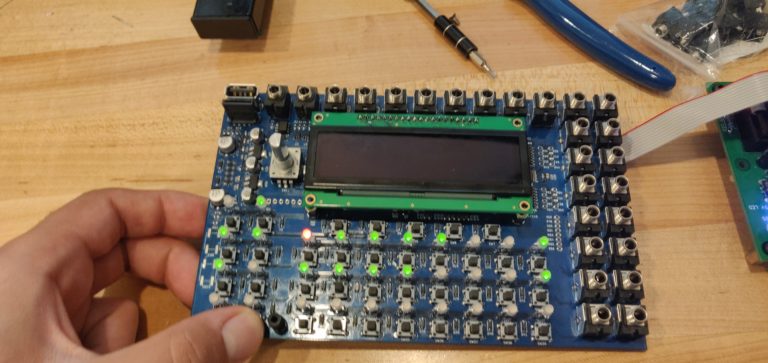
Finally, we are here. The point of booting this little guy up.
Here we go!…..
….And something is wrong here. No big beautiful display. The buttons, LEDs, and functionality seem to be there, but where’s my OLED?
After some gentle weeping, I start troubleshooting. Power is getting to the display just fine, all my voltages seem correct everywhere. I removed the pins, and re-soldered the display… No luck.
I desperately posted on Muffwiggler. I eventually gave up and ordered a new OLED.
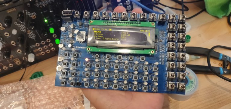
No magic this time, just a defective OLED. Sometimes things are that simple.
LOOK HOW BEAUTIFUL IT IS
OHHHHH BABY. I owe you one Simon. I made a schematic for a 2.1GHz triple attenuverter I’ll DM you one day. It’s a doosey.
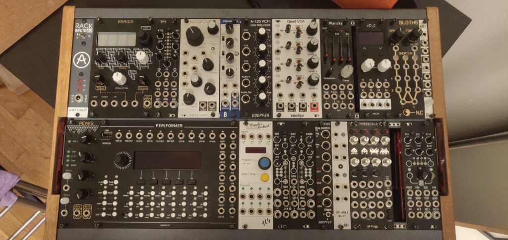
Got some buttons and the spacers on there. And MMM MMM. Look how good it looks nestled into my Rackbrute.
This was a lot of fun, and the actual use of this machine is unreal. Very quick and intuitive. The best devices are born out of need, and this is the kind of sequencer I knew I wanted, but didn’t know I needed.
OK that was dramatic. But really, I love this thing. My only concern is the PCB flex when you click some of these buttons, but it doesn’t detract from how useful this beast is.
If it wasn’t already clear, I’ve been using it for the following (not an exhaustive list):
Master clock
Midi in/out through TRS cables
8 independent gate and CV outputs
CV outs are capable of quantized V/Oct signals, or sending complex CV signals for modulation
Retrigger and conditional triggers like you wouldn’t believe
So, it’s gnarly. I think I may write up a little glowing review in another blog post, but I whole heartedly recommend this module to anyone who thinks they’re up to some SMD, even if you don’t think you need a sequencer. This thing is rock solid.
The Quickest Links
Mouser BOM (missing all jacks, button caps, spacers)
PS you did spot a Threshold in the rack… Keep your eyes peeled for a Jak Plugg Threshold build diary and a 16n faderbank build diary in the near future! YOU KNOW I LOVE MY JAK PLUGGZ.
I am building one now. I have not installed the LEDs. Running tester.hex the led red and green are backwards from what the test indicates. The build instructions say to put the shortest lead in the square pad hole. Is this wrong?
I was checking out your build blog for the Performer. Do you still check this blog? I love you have the Mouser cart link on this page, but there is one problem. What do I do for the obsolete parts or long lead time parts? Any help would be greatly appreciated! Thanks!
Hey there! Yes, definitely, but not as much as I used to sadly. For the obsolete parts or ones with long lead times you can try to find drop in replacements. Usually with obsolete parts there is always some kind of replacement that is out there for it. But sometimes your stuck with long lead times or tracking down obsolete parts 🙁 which parts are you looking for? I can try to help.

I am building one now. I have not installed the LEDs. Running tester.hex the led red and green are backwards from what the test indicates. The build instructions say to put the shortest lead in the square pad hole. Is this wrong?
Thanks
I was checking out your build blog for the Performer. Do you still check this blog? I love you have the Mouser cart link on this page, but there is one problem. What do I do for the obsolete parts or long lead time parts? Any help would be greatly appreciated! Thanks!
Hey there! Yes, definitely, but not as much as I used to sadly. For the obsolete parts or ones with long lead times you can try to find drop in replacements. Usually with obsolete parts there is always some kind of replacement that is out there for it. But sometimes your stuck with long lead times or tracking down obsolete parts 🙁 which parts are you looking for? I can try to help.