We are back and we are doing some synth breadboarding! Or like, synth-adjacent breadboarding? We’re gonna get weird with some chips. Am I making sense yet?
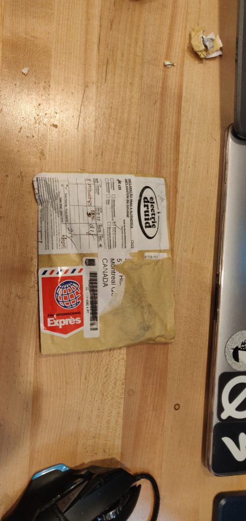
In a little blog from a bit ago I got all juiced up on some ICs from Electric Druid, and they finally made their way through our tired weary postal systems to my front door. Although I am an entitled Amazon Prime customer (I try so hard not to, but oh man that one day shipping is great), it showed up pretty quickly. Thanks Portugal!
Got these before the move to the new place, they had to sit unloved for so long.
One Shot Event Generator
So the little guy we’re looking at today, if the title didn’t give it away, is the One Shot Event generator. It’s a cute little chip that will send a CV signal out one end when it receives a gate signal at another. Electric Druid describes it best:
This new chip is a One-Shot Event Generator. It creates interesting unipolar modulation waveforms made from a one-shot ”ping”. You can alter the shape and speed of the ping, and also add decaying echos to it, with separate Delay and Repeats controls.
My favourite portion of the description being:
You’ll get a variety of “Sproing!”, “BOINGBOINGboingboing!”, and “BLIPBlipblipblipblipblip!” sounds, as well as “KRRaackrackrackrackrackrack!”, “Brrrrrrrrrrt!” and similar.
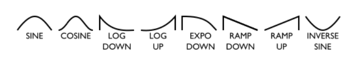
YESSS I love it. Give me the BLIP TOM. Check out some of the cool waveforms this puppy can spit out.
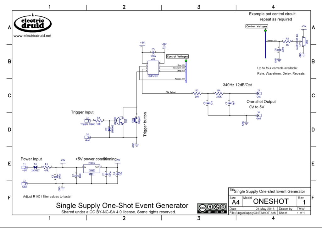
But I’m getting ahead of myself. I want to tell you that you choose the waveform with a potentiometer (DUH), but we haven’t even seen the circuit we’re up against today. CAN WE GET A CLOSE UP TOM.
YESSS TOM. YES.
The waveform is controlled by pin 6 on the IC. You also have the option to control the rate, delay between “shots”, and repeats. For this little board-bread I’m going to only control the waveform and repeats. Generously, Tom has provided some other schematics to get this chip powered and controllable.
I am going to ignore the power section, I have a little breadboard supply that can supply 5v from a Euro Rack power supply; nice and easy for providing juice.
I am also going to ignore the trigger input for the most part. I just have a button going to ground for reasons I’ll describe later, but lets get breadboarding!
Prototyping the Circuit
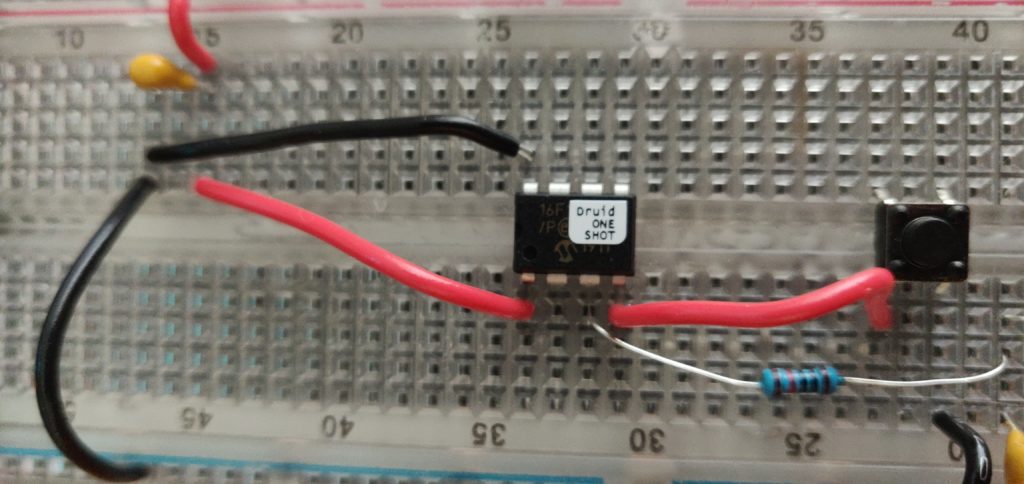
It’s time to get down to the nitty-gritty! Being as excited as I was, I just started slapping stuff onto the breadboard. Forgive me, young reader, I was so excited to do make something again.
Not the worst start...
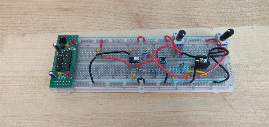
A couple wires and pots later and BAM.
OK OK, not great. But does it make sweet sweet CV?
You bet it does, but there were some blips. Or more like a couple BLIPBlipblipblipblipblips.
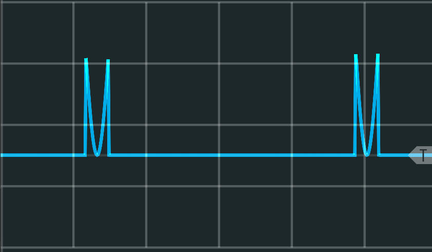
Show me those waveforms!
You’ve got it!
Ouuu fancy.
And everything was working great… but there were some weird things happening. Look at this one.
Very cool, but I don't see this option Tom.
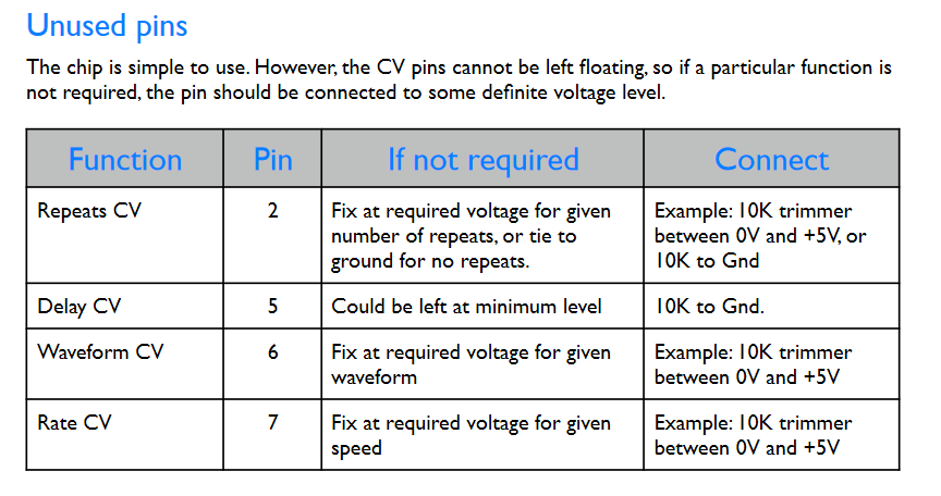
So rather than thinking I could leave pins on an IC just floating around like that, I decided to consult the datasheet.
Ohhhh. I'm learning.
So I ironed that out, but there was still the problem of the breadboard being a mess. I couldn’t even fit the trigger section onto a breadboard, and this is a rather simple circuit.
What is a boy to do?
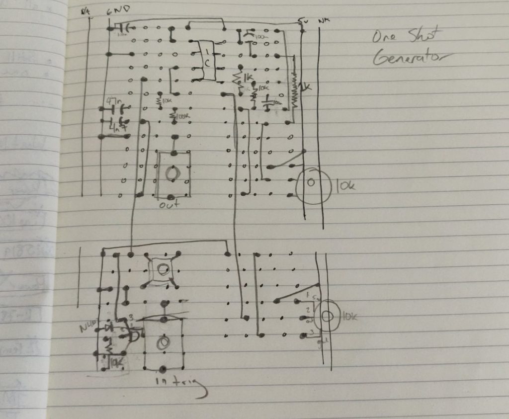
Back to the drawing...book?
Really I should have been doing this from the start, and I’m sure every got’ dang’ electronics blog out there gives you hot tips like this, but I do it my way here. Sketching out what you’re breadboarding is probably a good move, right? Tell past Steve, because future Steve is allll about penciling out circuits for clean breadboards. Check it out, I even fit the trigger section!
Yaaaas.
While you’re talking to future Steve, let him know there’s a few things you have to remember when you’re drawing circuits. Because this above drawing has some issues in the real world.
First, jumper cables to a row directly above or below the point you’re currently working with just do not work. You I can’t get the wire to bend into the termination points that close together. You totally can use resistors this way, or you’ve got to get some really thin jumper wire.
Second, using colours for different connections would make things more legible, leading to less errors when actually breadboarding the circuit. I went straight pencil on everything, but it would be good to have some visual representation of where the hot hot 5v is and where the earth be at. You know?
Third, just like, have fun, you know? It’s not a race. We’re all human beings out here. Just trying to live man. Just trying to live.
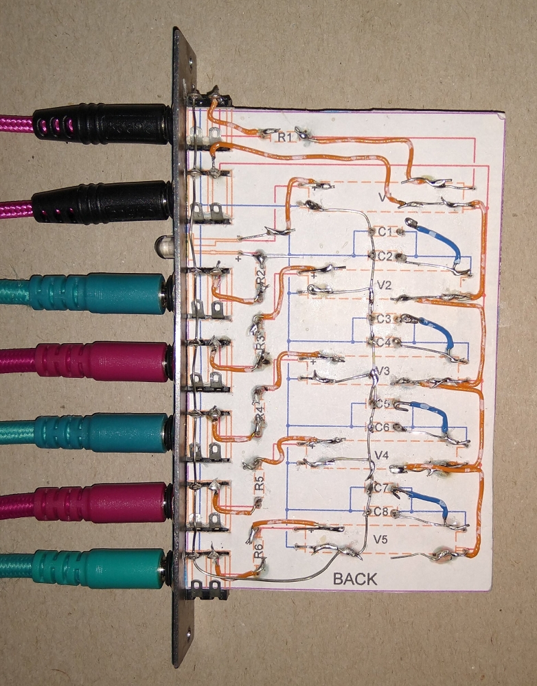
And before I go for the week… CHECK OUT THIS PAPER PCB.
Only cool to me? Oh, you already knew this was a thing? Cool cool.
ALRIGHTY that about does it for this funday Sunday. Thanks for coming back and reading my drivel. I hope you find it informative, or at the very least, entertaining.
The future? Well, we got the LYRA-8 on route, SWN, lots more Electric Druid goodness, Deckard’s Dream, and very very soon, I’ll be throwing together an MBrane.
YOU KNOW I COULDN’T STAY AWAY MUCH LONGER JAKPLUGG. DADDY’S HOME.